Contact Person: Angeliki Chondrou aggeliki1811@gmail.com;
This study refers to the investigation of the dynamic behavior and stability of emulsions under low gravity conditions evolving during parabolic flights. Emulsions are systems consisting of two immiscible liquids. On earth, buoyancy makes an emulsion separate rapidly into two distinct layers and, as a result the motion of droplets and droplet-droplet interactions (coalescence and aggregation) that strongly affect emulsion destabilization cannot be investigated in depth. Microgravity, on the other hand, provides a simplified environment where gravity driven processes are eliminated, the motion of droplets and droplet-droplet interactions (coalescence, aggregation) get slower and, as a result, can be studied both thoroughly and individually employing conventional diagnostics (e.g. optical and electrical methods).
An experimental setup is manufactured for the production and dynamic behavior/stability study of emulsions. The core of the device is the emulsification unit (Fig 1), which is based on a miniature pulsating emulsification setup already developed and successfully tested by Multiphase Dynamics Group (see Research Project: Development of an Innovative miniature emulsification device). The most important part of the emulsification unit is an aluminum experimental cell. Two of the parallel cell walls are made of glass offering ports for optical recordings and lighting. The other two (parallel) plexiglass walls have flush-mounted metallic electrodes for performing electrical measurements. A cylindrical piston is integrated to the lid of the cell. The tip of the piston ends to a thin aluminum plate which covers almost the entire cross section (Fig 2). During emulsification, the piston moves continuously up and down along the perpendicular axis, scavenging the total internal volume of the cell. The piston plate has orthogonal shape of uniform height. The height is 1.62 mm while the gap between the plate and the cell walls is 0.66 mm. The design of the device to be used during the Parabolic Flights includes the frame of the emulsification unit in which the motor is integrated and a case that supports five identical experimental cells. The cell case is placed in a carrier which gives the opportunity different experimental cell to be used in each parabola.
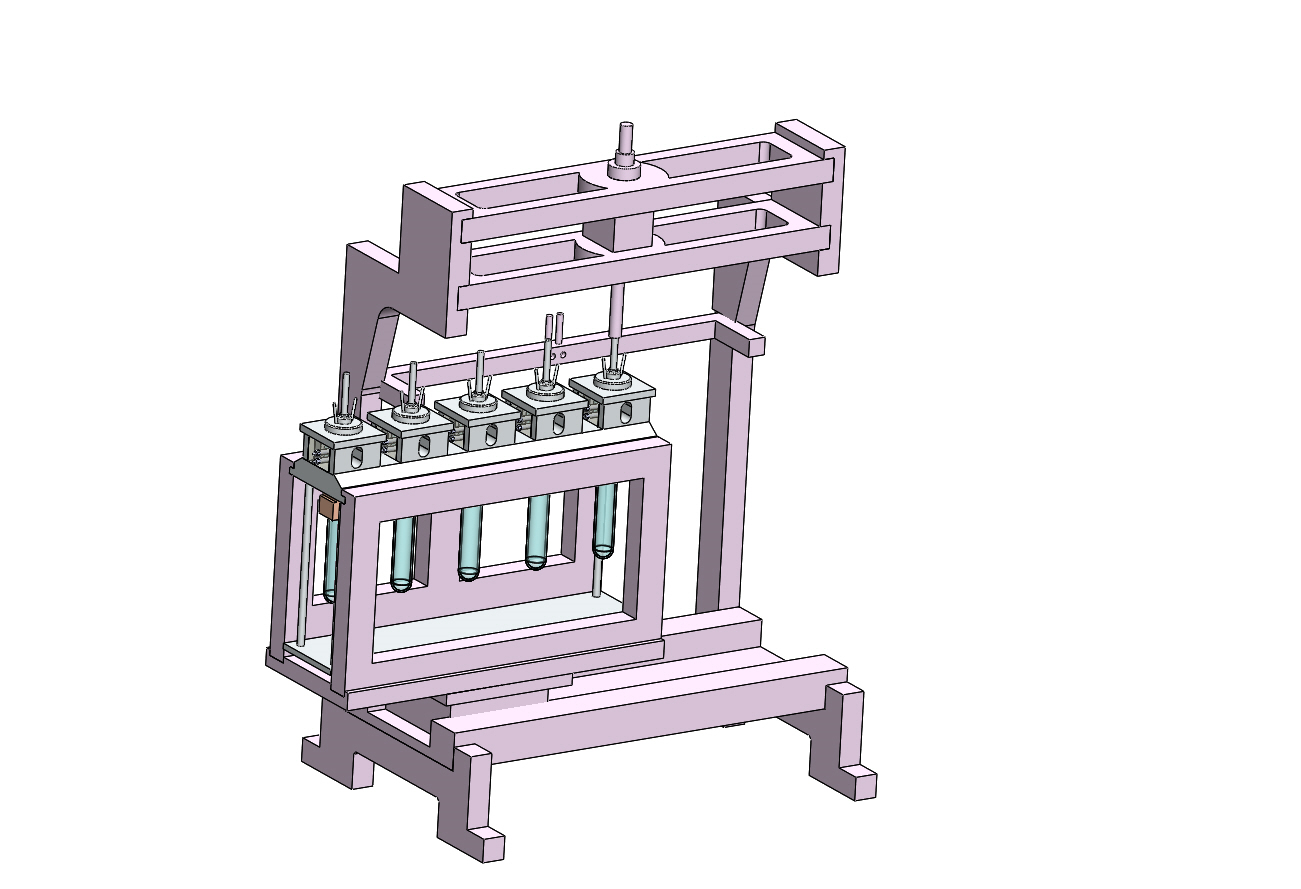
Fig 1. Emulsification Unit
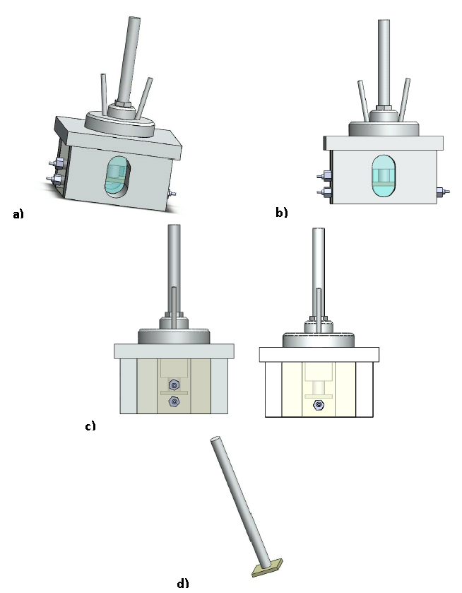
Fig 2. a) Experimental cell, b) Glass cell walls for optical recordings and lighting; c) Plexiglass walls with flush-mounted metallic electrodes for conducting electrical measurements; d) Piston
Two different cameras will be used to monitor droplets breakup/motion and to capture images in order to determine oil droplet size distribution. An optical diagnostics unit is designed to incorporate the two cameras in combination with a cube beam splitter that enables simultaneous optical recording of the emulsion by the two cameras (Fig 3). The exact position of the two cameras can be fine-tuned in the X, Y and Z axis by using proper micromanipulators (Fig 3). A Photron FASTCAM Multi high speed camera will be used to monitor droplets breakup during emulsification and droplets motion after the emulsification process end. A CANON EOS 70D digital camera with a frame resolution of 20MP, supported by CANON EF 100mm f/2.8 Macro USM Lens and six CANON extension rings for magnification will be used to capture the oil droplets of the produced emulsion.
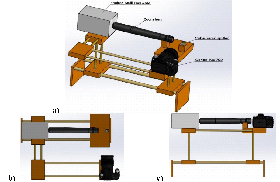
Fig 3. Optical diagnostics unit (a) overview, (b) top view, (c) back view
Moreover, I-VED, an electrical impedance spectroscopy technique (EP 3 005 942 A1, 2016) will be used to estimate oil volumetric fraction evolution and, further, to validate droplet size distributions derived from optical measurements. A dedicated I-VED version will be used during experiments in parabolic flights which realizes the essential functions of a) signal generation, b) data acquisition (Fig 4) and c) resistance termination.
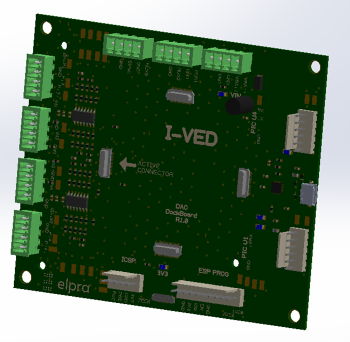
Fig 4. Data Acquisition Card 3D Drawing
The experimental setup overview is presented in Fig 5.
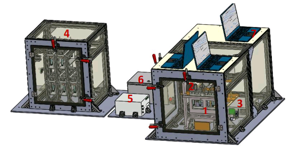
Fig 5. Experimental setup overview; 1- Emulsification unit, 2- Optical diagnostics unit, 3- Electrical diagnostics unit, 4- Cell cases΄ storage unit, 5- Multi FASTCAM Processor, 6- Control Panel, 7- Laptop